Converting a Dance Dance Revolution mat to USB
by Etienne Millon on November 27, 2014
Abstract: I transform a Playstation/parallel port converter to USB. This includes finding the pinout of the previous circuit, making an AVR toolchain work, and writing the firmware. Some bugs are found, and fixed. The result is open source.
Do you pine for the days when people were people and wrote their own device drivers? Some days are still like that, you just have to take the opportunity.
Recently while organizing my place I found two abandoned items that were meant to meet each other: a Dance Dance Revolution mat and a Teensy++ development board. This project is the story of their union.
Finding the pinout
So, I stumbled upon an old DDR mat and I wanted to play with it. The easiest way is using Stepmania, a simulator that works on Linux (and that I am trying to package for Debian). But some interface is needed to connect dancing mats (usually made for the Playstation) to a computer.
In a previous life I replaced the Playstation connector of this mat with a parallel port connector. In the beginning of the 2000s, the popular circuit to do this was Direct Pad Pro, and on Linux there was a similar driver documented in joystick-parport.txt.
Needless to say, I do not have a parallel port on my computer anymore, so some conversion is required. I also happen to have a USB development board on hand, so a possible solution is to program it to drive the Playstation mat.
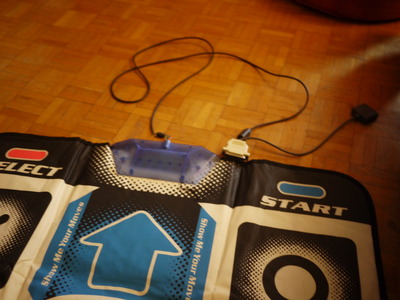
On the above picture, two things are connected to the parallel port: the DDR mat and a female SNES connector. The driver indeed supported several gamepads, even of different types.
The first step was to note the pinout of the existing connection:
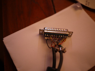
DB25

 2 ───────── orange
 3 ───────── yellow
 4 ───────── blue
 5 ──▷|─┐
 6 ──▷|─┤
 7 ──▷|─┼─── pink
 8 ──▷|─┤
 9 ──▷|─┘
11 ───────── brown
19 ─────┐
20 ─────┤
21 ─────┤
22 ─────┼─── black
23 ─────┤
24 ─────┤
25 ─────┘
      NC  ── green
Looking at the kernel documentation, it means that the 11 is the data pin for the Playstation connector (the SNES pad was #1 and the PSX pad was #2).
This was enough to reconstruct the correct pinout. Note that the kernel numbers PSX pins in the opposite order of everything else I have seen. The following table uses kernel order.
| Color | DB25 # | PSX # | Function |
|---|---|---|---|
| orange | 2 | 8 | Command |
| yellow | 3 | 4 | Select |
| blue | 4 | 3 | Clock |
| pink | 5-9 1 | 5 | Vcc |
| brown | 11 | 9 | Data |
| black | 19-25 | 6 | Ground |
| green | NC |
At first, I was worried by the green wire that was not connected but this confirms that it was not needed.
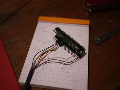
Connecting it to the teensy++
The teensy++ is a development board with an AT90USB1286 microcontroller, from the AVR family. It has many GPIO ports, so I had to make a choice regarding the pins to be used. I chose this pinout:
| AVR port | Color | Function | Direction |
|---|---|---|---|
| Vcc | pink | Vcc | Power |
| GND | black | Ground | Power |
| PC0 | brown | Data | D→H |
| PC1 | orange | Command | H→D |
| PC2 | yellow | Select | H→D |
| PC3 | blue | Clock | H→D |
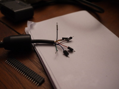
The Data signal is the only one that goes from the Device (DDR mat) to the Host (microcontroller), but since each pin can be used as an input or as an output, this does not constrain the choice.
So, let’s connect the DDR mat to the microcontroller. As the board already has male pin headers for breadboard usage, I soldered female pin headers to wires.
Programming the teensy++
I had two main problems writing the firmware: first, the manufacturer seems to recommend Teensy Loader to program the microcontroller. This is a GUI app and which does not seem to be free software. Fortunately, I found a packaged version of teensy-loader-cli which is CLI, GPL3, and works well. The following command will program the microcontroller:
teensy-loader-cli -mmcu=at90usb1286 blink_slow_Teensy2pp.hexThe second quirk is that most of the documentation that can be found is for
using the teensy++ as an Arduino. But I prefer writing low-level code: just
memory-mapped registers, a C compiler, and me. So I aptitude-installed gcc-avr
and avr-lib and opened vim.
There are several differences in how you program microcontrollers as an Arduino and as a plain AVR. For example here is how you configure PC0 to be an input with a pull-up resistor (so that it reads 1 when the pin is disconnected):
DDRC &= ~(1 << PC0);
PORTC |= (1 << PC0);
This clears bit PC0 of register DDRC (Data Direction Register C, nothing to do with Dance Dance Revolution) and sets bit PC0 of the PORTC register. Instead, the corresponding Arduino code is:
pinMode(10, INPUT_PULLUP);To do that, the library has a mapping from pin numbers (an Arduino-specific terminology, it seems) to register names.
The PSX protocol
Time to write the code itself. My absolute reference for programming and interfacing the Playstation is Everything You Have Always Wanted to Know about the Playstation But Were Afraid to Ask. See section 9 for controllers.
The idea is that every frame (16 ms), Select becomes low, and bytes are transfered, LSB first, in a synchronous way over the Command (D→H) and Data (H→D) pins. Select becomes high back again after all bytes are transfered.
This means that every time a bit is transfered to the gamepad, a bit is read at the same time. For every bit, the following operations are needed:
- set Command according to the bit to transmit;
- put Clock down;
- wait half a clock cycle;
- read Data: that is the bit received;
- put Clock up;
- wait half a clock cycle.
Or, if you prefer in C:
static uint8_t transmit(uint8_t in)
{
        uint8_t out = 0;
        for (int i = 0; i < 8 ; i++) {
                int bit_in = in & (1 << i);
                if (bit_in) {
                        signal_up(PSX_PIN_CMD);
                } else {
                        signal_down(PSX_PIN_CMD);
                }
                signal_down(PSX_PIN_CLOCK);
                _delay_us(DELAY_CLOCK_US);
                int bit_out = signal_read(PSX_PIN_DATA);
                if (bit_out) {
                        out |= (1 << i);
                } else {
                        out &= ~(1 << i);
                }
                signal_up(PSX_PIN_CLOCK);
                _delay_us(DELAY_CLOCK_US);
        }
        return out;
}
During a normal operation, the bytes exchanged should be the following:
| Byte # | Command | Data |
|---|---|---|
| 1 | 0x01 | 0xFF |
| 2 | 0x42 | 0x41 |
| 3 | 0x00 | 0x5A |
| 4 | 0x00 | data1 |
| 5 | 0x00 | data2 |
Keypress information can be found in the 16-bit number (data2 << 8) | data1).
If a bit is 0, it means that the corresponding button is pressed.
| Bit # | Key | Bit # | Key |
|---|---|---|---|
| 0 | Select | 8 | L2 |
| 1 | (always 1) | 9 | R2 |
| 2 | (always 1) | 10 | L1 |
| 3 | Start | 11 | R1 |
| 4 | Up | 12 | Triangle |
| 5 | Right | 13 | Circle |
| 6 | Down | 14 | Cross |
| 7 | Left | 15 | Square |
At first, it was not obvious how to debug the implementation of this protocol. Fortunately, this microcontroller has a USB port and it is possible to transmit debug messages using the usb_debug_only code sample from the manufacturer.
With no real surprise, my first iteration did not work and printed the following.
01 -> FF
42 -> FF
00 -> FF
00 -> FF
00 -> FF
I re-read my code carefully and I found two bugs:
- I was not putting Clock back up.
- I was using PORTC for reading input even though PINC was needed… the registers are mapped in memory but not at the same address for reading and writing. Rookie mistake.
After reprogramming and reloading I saw a satisfying output:
01 -> FF
42 -> 41
00 -> 5A
00 -> FF
00 -> DF
The output bytes correspond to the device ID part (41 5A) and a value (FF DF) that indicates that nothing is pressed except the Circle button.
Interfacing with the computer
At that moment the firmware just computes the result and prints it over USB. To
do something useful with it on the computer side, this information needs to be
exposed as a USB joystick or keyboard. I used the usb_keyboard code sample
which exports a usb_keyboard_press function.
It was necessary to slightly alter the main loop: in a debug setting it is
possible to print the state at every frame, but a keyboard works differently.
You are supposed to send a message only when a key is pressed. So, at each
frame, it is necessary to keep track of the previous state and to diff it with
the current one. If a bit was previously set (meaning that the button is not
pressed) and is now set, the USB code has to be notified that a key was pressed.
This code is run for every btn if the state changes:
int was_released = last_js & (1 << btn);
int is_pressed = !(js & (1 << btn));
if (was_released && is_pressed) {
        int key = mapping[btn];
        usb_keyboard_press(key, 0);
}
This is simple, yet it works quite well and is enough to play Stepmania!
I noticed that however it does not work perfectly since the key is released immediately: this is a problem for DDR since the patterns where you have to hold keys do not work.
Let’s have a look at this function from the library:
int8_t usb_keyboard_press(uint8_t key, uint8_t modifier)
{
        int8_t r;
        keyboard_modifier_keys = modifier;
        keyboard_keys[0] = key;
        r = usb_keyboard_send();
        if (r) return r;
        keyboard_modifier_keys = 0;
        keyboard_keys[0] = 0;
        return usb_keyboard_send();
}
When usb_keyboard_send is called, it transmits the contents of keyboard_keys
over USB. All nonzero elements correspond to keys that are pressed. So what this
function does is transmit a state where a key is pressed, then transmit a state
where nothing is pressed.
This has two limitations:
- it does not separate key press from key release;
- it does not work if several keys are pressed at once.
Making rollover work
It would be nice to implement n-key rollover (NKRO) so that all keys can be
pressed independently. This is possible, by increasing the size of
keyboard_keys to 14 (the number of keys on a Playstation gamepad). But this
means fiddling with the USB descriptor code, so that the USB host side can know
how many bytes to expect, and I am not really comfortable with that.
In the library, the size of keyboard_keys is 6, so I stuck with 6-key rollover
which ought to be enough for everybody.
Here is the new version of the code that is called for every button:
int was_pressed = !(last_js & (1 << i));
int is_pressed = !(js & (1 << i));

if (is_pressed && !was_pressed) {
        keypress_add(mapping[i]);
}
if (was_pressed && !is_pressed) {
        keypress_remove(mapping[i]);
}
The keypress_add function walks the keyboard_keys array and replace the
first 0 with the correct button. keypress_remove does the opposite.
And… this works! I found this very refreshing to write low-level code for an existing, documented protocol. If you are interested, all the code can be found in this github repository. Thanks for reading!
Protected by 1N4148 diodes.↩︎